Filter Section
The Filter section allows you to adjust the tone color of the sound.
- Filter Shape
-
-
LP24, 18, 12, and 6 are low-pass filters with 24, 18, 12, and 6 dB/oct. Frequencies above the cutoff are attenuated.
-
BP12 and BP24 are band-pass filters with 12 and 24 dB/oct. Frequencies below and above the cutoff are attenuated.
-
HP6 + LP18 and HP6 + LP12 are a combination of a high-pass filter with 6 dB/oct and a low-pass filter with 18 and 12 dB/oct, respectively (asymmetric band-pass filter). Frequencies below and above the cutoff are attenuated. Attenuation is more pronounced for the frequencies above the cutoff.
-
HP12 + LP6 and HP18 + LP6 are a combination of a high-pass filter with 12 and 18 dB/oct and a low-pass filter with 6 dB/oct (asymmetric band-pass filter). Frequencies below and above the cutoff are attenuated. Attenuation is more pronounced for the frequencies below the cutoff.
-
HP24, 18, 12, and 6 are high-pass filters with 24, 18, 12, and 6 dB/oct. Frequencies below the cutoff are attenuated.
-
BR12 and BR24 are band-reject filters with 12 and 24 dB/oct. Frequencies around the cutoff are attenuated.
-
BR12 + LP6 and BR12 + LP12 are a combination of a band-reject filter with 12 dB/oct and a low-pass filter with 6 and 12 dB/oct, respectively. Frequencies around and above the cutoff are attenuated.
-
BP12 + BR12 is a band-pass filter with 12 dB/oct plus a band-reject filter with 12 dB/oct. Frequencies below, above, and around the cutoff are attenuated.
-
HP6 + BR12 and HP12 + BR12 are a combination of a high-pass filter with 6 and 12 dB/oct and a band-reject filter with 12 dB/oct. Frequencies below and around the cutoff are attenuated.
-
AP is an all-pass filter with 18 dB/oct. Frequencies around the cutoff are attenuated.
-
AP + LP6 is an all-pass filter with 18 dB/oct plus a low-pass filter with 6 dB/oct. Frequencies around and above the cutoff are attenuated.
-
HP6 + AP is a high-pass filter with 6 dB/oct plus an all-pass filter with 18 dB/oct. Frequencies around and below the cutoff are attenuated.
-
- Cutoff
-
Controls the cutoff frequency of the filter.
- Resonance
-
Emphasizes the frequencies around the cutoff. At higher settings, the filter self-oscillates, which results in a ringing tone.
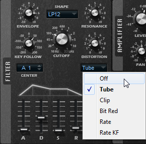
- Distortion
Adds distortion to the signal. The following distortion types are available:
Tube adds warm, tube-like distortion.
Clip adds bright, transistor-like distortion.
Bit Red (Bit Reduction) adds digital distortion by means of quantization noise.
Rate adds digital distortion by means of aliasing.
Rate KF adds digital distortion by means of aliasing, and it also includes Key Follow. The rate reduction follows the keyboard, that is, the higher the note that you play, the higher the sample rate.
If this is set to Off, no filter distortion is applied.
- Envelope
Adjusts the cutoff modulation of the filter envelope. Negative values invert the modulation direction.
- Key Follow
Adjusts the cutoff modulation using the note number.
If this is set to positive values, you raise the cutoff with notes above the center key.
If this is set to negative values, you lower the cutoff with notes above the center key.
If this is set to 100 %, the cutoff follows the played pitch exactly.
The Center parameter determines the MIDI note that is used as the central position for the Key Follow function.
- Envelope and Velocity Controls
The A, D, S, and R faders below the envelope display specify the attack, decay, sustain, and release times of the filter envelope.
The Velocity fader determines how much the envelope intensity depends on velocity. If the fader is set to 0, the envelope is fully applied. Higher values reduce the intensity for lower velocities.