Auto Filter
Auto Filter provides two morphable filter shapes with distortion.
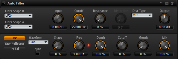
The morphing between the two shapes, as well as the cutoff, can be controlled with a manual pedal control, an LFO, or an envelope follower.
Filter Parameters
- Filter Shape
LP 24, 18, 12, and 6 are low-pass filters with 24, 18, 12, and 6 dB/oct. Frequencies above the cutoff are attenuated.
BP 12 and BP 24 are band-pass filters with 12 and 24 dB/oct. Frequencies below and above the cutoff are attenuated.
HP 6+LP 18 and HP 6+LP 12 are combinations of a high-pass filter with 6 dB/oct and a low-pass filter with 18 and 12 dB/oct, respectively (asymmetric band-pass filter). Frequencies below and above the cutoff are attenuated. Attenuation is more pronounced for the frequencies above the cutoff.
HP 12+LP 6 and HP 18+LP 6 are combinations of a high-pass filter with 12 and 18 dB/oct and a low-pass filter with 6 dB/oct (asymmetric band-pass filter). Frequencies below and above the cutoff are attenuated. Attenuation is more pronounced for the frequencies below the cutoff.
HP 24, 18, 12, and 6 are high-pass filters with 24, 18, 12, and 6 dB/oct. Frequencies below the cutoff are attenuated.
BR 12 and BR 24 are band-reject filters with 12 and 24 dB/oct. Frequencies around the cutoff are attenuated.
BR 12+LP 6 and BR 12+LP 12 are combinations of a band-reject filter with 12 dB/oct and a low-pass filter with 6 and 12 dB/oct, respectively. Frequencies around and above the cutoff are attenuated.
BP 12+BR 12 is a band-pass filter with 12 dB/oct plus a band-reject filter with 12 dB/oct. Frequencies below, above, and around the cutoff are attenuated.
HP 6+BR 12 and HP 12+BR 12 are combinations of a high-pass filter with 6 and 12 dB/oct and a band-reject filter with 12 dB/oct. Frequencies below and around the cutoff are attenuated.
AP is an all-pass filter with 18 dB/oct. Frequencies around the cutoff are attenuated.
AP+LP 6 is an all-pass filter with 18 dB/oct plus a low-pass filter with 6 dB/oct. Frequencies around and above the cutoff are attenuated.
HP 6+AP is a high-pass filter with 6 dB/oct plus an all-pass filter with 18 dB/oct. Frequencies around and below the cutoff are attenuated.
- Input
Adjusts the gain before the filter and distortion. This parameter only affects the wet signal.
- Cutoff
Specifies the cutoff frequency of the filter.
- Resonance
Emphasizes the frequencies around the cutoff. At higher resonance settings, the filter self-oscillates, which results in a ringing tone.
- Distortion Type
-
The following options are available:
-
When this parameter is set to Off, the filter offers no distortion.
-
Tube Drive adds warm, tube-like distortion.
-
Hard Clip adds bright, transistor-like distortion.
-
Bit Red adds digital distortion by means of quantization noise.
-
Rate Red adds digital distortion by means of aliasing.
-
- Distortion
Adds distortion to the signal. The effect depends on the selected distortion type. At higher settings, it creates a very intense distortion effect.
NoteThis parameter is not available if Distortion Type is set to Off.
- Output
Adjusts the gain after the filter and distortion. This parameter only affects the wet signal.
- Mix
Sets the ratio between the dry and the wet signal.
LFO Section
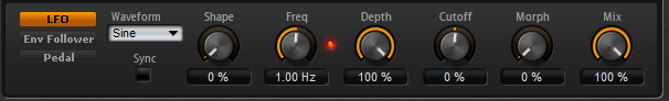
- LFO Waveform and Shape
Waveform selects the basic type of waveform. Shape changes the characteristic of the waveform.
Sine produces smooth modulation. Shape adds additional harmonics to the waveform.
Triangle is similar in character to Sine. The waveform periodically ramps up and down. Shape continuously changes the triangle waveform to a trapezoid.
Saw produces a ramp cycle. Shape continuously changes the waveform from ramp down to triangle to ramp up.
Pulse produces stepped modulation, where the modulation switches abruptly between two values. Shape continuously changes the ratio between the high and low state of the waveform. At 50 %, it produces a square wave.
Ramp is similar to the Saw waveform. Shape increasingly puts silence before the sawtooth ramps up.
Log is a logarithmic curvature. Shape continuously changes the curvature from negative to positive.
S & H 1 produces random stepped modulation, where each step is different. Shape puts ramps between the steps and produces a smooth random signal when fully turned right.
S & H 2 is similar to S & H 1. The steps alternate between random high and low values. Shape puts ramps between the steps and produces a smooth random signal when fully turned right.
- Freq
Determines the frequency of the cutoff modulation.
- Sync
Activate this to set the Freq parameter in fractions of beats.
- Depth
Determines the output level of the LFO modulation signal.
- Cutoff
Determines the modulation intensity of the LFO on the filter cutoff.
- Morph
Determines the modulation intensity of the LFO on the filter morph.
Envelope Follower Section
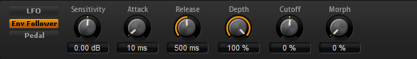
The Envelope Follower traces the input signal with an adjustable attack and release time and delivers a modulation signal representing the level envelope of the signal.
- Sensitivity
All input signals are mixed down to mono before they are sent to the Envelope Follower. This parameter sets the optimum input level for the Envelope Follower.
- Attack
Adjusts the attack time, that is, the time the Envelope Follower needs to approach increasing input levels.
- Release
Adjusts the release time, that is, the time the Envelope Follower needs to approach decreasing input levels.
- Depth
Determines the output level of the modulation signal of the Envelope Follower.
- Cutoff
Determines the modulation intensity of the Envelope Follower on the filter cutoff.
- Morph
Determines the modulation intensity of the Envelope Follower on the filter morph.
Pedal Section
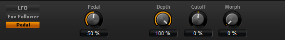
- Pedal
Sets the position of the pedal.
- Depth
Determines the output level of the pedal modulation signal.
- Cutoff
Determines the modulation intensity of the pedal on the filter cutoff.
- Morph
Determines the modulation intensity of the pedal on the filter morph.