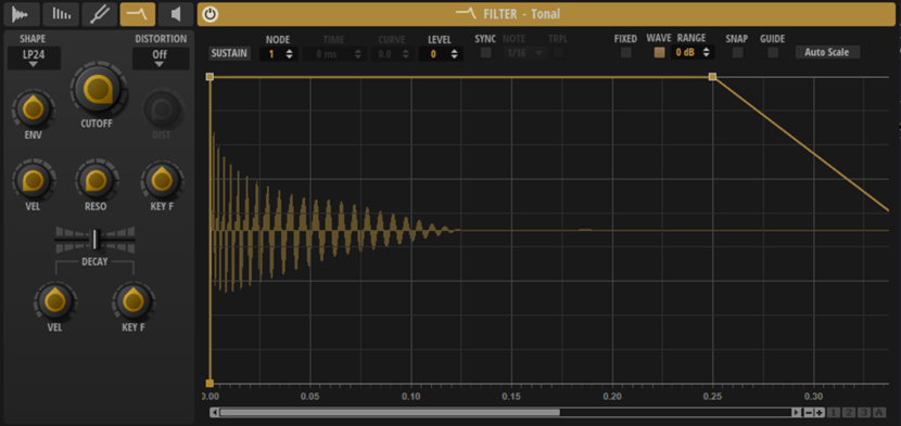
Filter Page
The Filter page lets you set up the filter and the filter envelope.
- Filter Shape
-
-
LP24, 18, 12, and 6 are low-pass filters with 24, 18, 12, and 6 dB/oct. Frequencies above the cutoff are attenuated.
-
BP12 and BP24 are band-pass filters with 12 and 24 dB/oct. Frequencies below and above the cutoff are attenuated.
-
HP6 + LP18 and HP6 + LP12 are a combination of a high-pass filter with 6 dB/oct and a low-pass filter with 18 and 12 dB/oct, respectively (asymmetric band-pass filter). Frequencies below and above the cutoff are attenuated. Attenuation is more pronounced for the frequencies above the cutoff.
-
HP12 + LP6 and HP18 + LP6 are a combination of a high-pass filter with 12 and 18 dB/oct and a low-pass filter with 6 dB/oct (asymmetric band-pass filter). Frequencies below and above the cutoff are attenuated. Attenuation is more pronounced for the frequencies below the cutoff.
-
HP24, 18, 12, and 6 are high-pass filters with 24, 18, 12, and 6 dB/oct. Frequencies below the cutoff are attenuated.
-
BR12 and BR24 are band-reject filters with 12 and 24 dB/oct. Frequencies around the cutoff are attenuated.
-
BR12 + LP6 and BR12 + LP12 are a combination of a band-reject filter with 12 dB/oct and a low-pass filter with 6 and 12 dB/oct, respectively. Frequencies around and above the cutoff are attenuated.
-
BP12 + BR12 is a band-pass filter with 12 dB/oct plus a band-reject filter with 12 dB/oct. Frequencies below, above, and around the cutoff are attenuated.
-
HP6 + BR12 and HP12 + BR12 are a combination of a high-pass filter with 6 and 12 dB/oct and a band-reject filter with 12 dB/oct. Frequencies below and around the cutoff are attenuated.
-
AP is an all-pass filter with 18 dB/oct. Frequencies around the cutoff are attenuated.
-
AP + LP6 is an all-pass filter with 18 dB/oct plus a low-pass filter with 6 dB/oct. Frequencies around and above the cutoff are attenuated.
-
HP6 + AP is a high-pass filter with 6 dB/oct plus an all-pass filter with 18 dB/oct. Frequencies around and below the cutoff are attenuated.
-
- Distortion Type
-
Lets you select a distortion type.
-
Tube adds warm, tube-like distortion.
-
Hard Clip adds bright, transistor-like distortion.
-
Bit Reduction adds digital distortion by means of quantization noise.
-
Rate Reduction adds digital distortion by means of aliasing.
-
Rate Reduction Key Follow adds digital distortion by means of aliasing, but with Key Follow. The rate reduction follows the keyboard, so the higher you play, the higher the sample rate.
-
Select Off if you do not want to apply any distortion.
-
- Distortion
-
Sets the amount of distortion.
- Envelope Amount
-
Controls the cutoff modulation from the filter envelope.
- Cutoff
-
Controls the cutoff frequency of the filter.
- Cutoff Velocity
-
Controls the cutoff modulation from velocity.
Increasing Cutoff Velocity moves the cutoff towards the lower frequencies when lower velocity values are received. The Cutoff value is then reached with the maximum velocity.
- Resonance
-
Emphasizes the frequencies around the cutoff. At higher settings, the filter self-oscillates, which results in a ringing tone.
- Cutoff Key Follow
-
Adjusts the cutoff modulation using the note number. Increase this parameter to raise the cutoff with higher notes. At 100%, the cutoff follows the played pitch exactly.
- Decay Time
-
Allows you to offset the decay time of the envelope, that is, all segments after the first node.
If Sustain Mode is activated, this parameter also affects the release phase.
- Decay Velocity
-
Adjusts the influence of velocity on the Decay Time. Positive values decrease the decay for higher velocity values. Negative values increase the decay for higher velocity values.
- Decay Key Follow
-
Adjusts the influence of the played key on the Decay Time. Positive values decrease the decay for keys above C3. Negative values increase the decay for keys above C3.